
Ham radios are like women, sports cars, airplanes, and sailboats. Your enjoyment of any of these will depend on careful consideration of your “use case”.
However, if your use case is “spend all your money” my experiments indicate that even a thoughtless collection of two or three of the above will work fine.
Which has what to do with Ham Radio and Comms at the End of the World? Ah…
Dr. John’s Email
You can imagine how pleased I was this week when an email popped in with a fascinating question:
“What type of antenna would you be considering if the following (were conditions)?
1. Tall pine trees killed by beetles and fire.
2. Storms with winds gusting to 125mph.
3. Solar storms.
4. Electric grid reliability is poor.
I’m thinking that permanent antennas are less viable in the above conditions. My self-supporting tower and beam can probably handle it, but maybe not. Although I like end-feds, there may not be trees nearby to pull them up. Instead, I have a 35-ft fiberglass mast, for which I have a post in concrete waiting for it.
Operators may be limited to CW or digital modes. Would a magnetic loop antenna be easier?”
Dr. John doesn’t explicitly say so, but we can assume his question involves beyond line-of-sight comms, the sort impossible with GMRS/FRS.
The Magic of HF Radio
The useful fascination is that the AM broadcast band is mainly a “ground wave” spectrum during the day. While the FM spectrum is (99.6 percent) Line-of-Sight. (You will still get atmospheric “bounce” (*CBer “skip”) with odd sun conditions – but it’s fairly rare. When it happens, I’ve worked 2-meter ham repeaters out at the 300-mile range…but that’s not in Dr. John’s question pool.
This underscores the need – when you are designing for repeatable success – to fill in as many use case variables as you can. The more variables, the more you can “solve” in terms of frequency and antenna.
Let me take you “Inside George’s brain” to learn about problem-solving and engineering flow of such problems. We’re going high-level, first. That will be the “engineering mind.” After that, we look at the Prepping Holes when comes to EM_COMMs. And the final part? My antenna picks.
Now “the band is going long” on us:
- “If you’re here for antenna picks, jump to Section 4.”
- “If you’re building the whole kit, keep reading.”
- “Both matter, depending on your use case.”
1. Engineering Always Begins Top-Down
Failure to “begin at the beginning” as Pappy taught, would always result in an overlooked aspect of (engineering or any other) problems. (Ask Boeing about dual angle-of-attack indicators). They will come back to bite.
When such oversights occur, the formal engineering notation is an F-function (f*k$#%) or an S-function (s**t%^&*()). All avoidable by a ruthless commitment to top-down process.
We can (inference is dangerous, use sparingly) Dr. John is talking HF (the VHF choice is covered) but he hasn’t called out in his use case either time of year or day part which will be operated.
Day parts are important. The F2 layer (where the MUF sets the upper reflectivity of the HF spectrum) is frequency dependent. So, while the MUF may leave 7 MHz usable until 8 AM local time, distance (DX) AM stations may begin to fade earlier, and the 160 Meter (1.8-2 MHz) band could be closing. And the opposite at night. East Coast stations can come in earlier on 10 MHz than on 3.8 MHz, for example.
This gets us to the second process chart – and this one in antennas selection becomes critical.
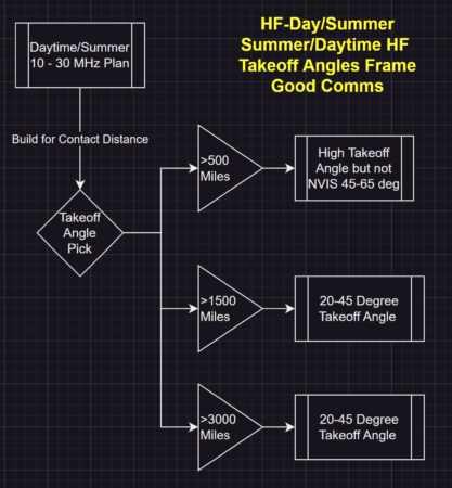
For every minute of the day, there is an ideal takeoff angle for an associated path distance, at a particular latitude, and time of year, and geomagnetic index, and…
Well, you get the idea…this is a multivariate problem. We can nail down loose ends in a really critical decision path. Now let’s go realizable:
Disaster Flavors Matter
Two Use Cases for John:
- New Madrid quake blows a 9.7 temblor devastating the heartland. 1,800 mile path daytime.
- War overtakes Europe and NATO engages in defense of Poland. 4,000 mile path, mixed.
We need the “where to?” to solve for “how to.”
Solving for Dr. John
Since a few conditions (time of year, survivable structures, frequencies) are not specified, but we know John’s location, we can make some intelligent estimates.
Let’s assume somewhere in the Columbia River Gorge area, and likely on the “sane side” but here lately that’s become impossible to determine. Still, if you think of The Gorge in windsurfing circles, you’ll quickly understand that 125 MPH winds is not just some crackpot “out there.” John’s talking nearby possible with only minimal atmospheric upset required. (Like a nuke or three.)
I’ve seen credible handheld reports over 110 mph near Crown Point; official stations recorded lower, but either way…
The good news? With that much wind, it will only take a couple of the 24 volt composite blade wind machines to keep John’s radios on the air. They will self-feather at 65 MPH and above. So, if John is planning to work the 20-meter End of the World QSO Party, he may qualify for a contest point multiplier.
The bad news? Dr. John and bride (along with parts of Portland and Walla Walla) will still be airborne over Montana or the Dakotas somewhere…
The Take Off Angle Discussion
Here’s the part that separates “an antenna that tunes” from “an antenna that talks.”
We tend to think in frequency first: 40 meters for this, 20 meters for that. But in practice, once you have a workable frequency, the next question that decides success is launch angle — the takeoff angle of your signal as it leaves the antenna and heads upward toward the ionosphere. And frequency, of course.
Think of it like shooting pool in the dark.
A low-angle shot skims out across the table and travels a long way before it hits a cushion. That’s your long-haul DX pattern: under 15 degrees, sometimes 20 if conditions are soft. You’re throwing energy downrange, as low to the horizon as you can, trying to tag the next continent or the other side of the U.S.
A high-angle shot pops up, hits the cushion almost immediately, and comes back down near you. At the extreme (a direct-on bumper shot 90-degrees) that’s NVIS (Near Vertical Incidence Skywave):approaching 90 degrees. It’s the “talk to everyone in the next state or three” solution when the terrain is ugly, line-of-sight is a joke, and you don’t want to depend on repeaters or infrastructure.
Same band. Same watts. Completely different results — because you launched the energy at a different angle.
What controls takeoff angle? Height above ground relative to wavelength, and the antenna’s geometry. Ok ground conductivity (and more multivariates…)
The short version is this: when you hang a horizontal wire low — say 10–20 feet up on 40 meters — it behaves like a high-angle radiator. Great for 100–500 miles, sometimes out to 800 depending on band and conditions. Raise that same wire to a half-wave height and above (for 40 meters, think roughly 60–70 feet and up) and the pattern collapses downward. Now you’re feeding the low-angle lobes that win you distance.
Around one full wavelength up, say 120 feet, two things happen to the wire antenna. If it’s a dipole (two roughly 33-foot wires, fed at the middle) a broadside pattern becomes predominant. But working off the ends gets worse.
As if that isn’t complicated enough, what are called “ground effects” change takeoff depending on the electrical properties of the (physical) ground which is (normally) the RF ground.
Now here’s the paradox: in “end of the world” use cases, you don’t get to pick “perfect height.” You pick “survivable.” Or “Best under constraints.”
That’s why John’s 35-foot fiberglass mast matters. It’s a survivable, repeatable support. But it also imposes a physics choice: at 35 feet, you’re “high” on 20 meters, “middling” on 40, and “low” on 80. Which means the same mast can be made to favor either regional comms or long-haul comms depending on band and antenna style.
TOA Bottom line: If you only build one survivable HF setup, build it to do two angles: one high-angle (NVIS/regional) and one low-angle (reach-out/DX).
Action: Pre-cut and label two antenna kits now: “Regional” and “Distance.” Same mast, different wire. When the wind howls, you don’t “think,” you deploy.
2. Sorting Out the Use Cases
Next let’s map John’s two scenarios onto angles.
Use Case 1: New Madrid quake, daytime, 1,800-mile path.
Daytime, 1,800 miles, and likely a noisy, stressed HF environment. What John wants is not “a miracle hop.” He wants reliability.
A 1,800-mile daytime path is often a low-angle game on the higher HF bands if the ionosphere will support it — 20 meters and up — because you want to reach over the mid-zone and land out around the second/third skip. But if the higher bands are unsettled (solar storm effects, maybe so geo aftereffects), you may be forced down to 40 meters, where daytime can still work but the range and skip geometry can get finicky.
Most of my high school years were spent neglecting homework and doing 40 meter CW (Morse). From Seattle, I was in regular contact down to about Ashland (southern), Oregon. San Francisco or the NorCal area would pop in about 4 PM, or so, spring and fall. Later in summer, earlier in winter. See how much like a “radio version of fishing” this gets to be?
This is where a “single best antenna” (as a fishing rod) stops existing and you start building a “pattern kit.” If you’re serious about 1,800 miles as a mission, you want the ability to throw energy lower than an NVIS cloud-burner. That usually means either getting height (which John can’t count on in 125 mph), or using an antenna type that naturally supports lower-angle radiation with what you can actually erect.
Use Case 2: War in Europe, 4,000 miles, mixed day/night.
Now you’re firmly in DX country. 4,000 miles is not NVIS. It’s low-angle, multi-hop or long single-hop depending on band and conditions. Night will move the usable band choices downward (40 becomes a player, 20 may still run if the MUF stays up, 30 can be a sweet spot). Day will push you higher (20/17/15 if conditions allow).
The antenna implication is blunt: if your radiation is mostly going straight up, you can work the next state beautifully and never be heard in Poland. Conversely, if you build only for low-angle distance, your “regional net” might be weak when the local terrain and infrastructure are in chaos.
So what does a good RF engineer do? (Drink??? 807s or 4-1000s, sure…)
They don’t ask “What antenna is best?” They ask “What launch angles must I be able to produce?” Then they select antennas that cover those angles with the supports and weather reality they’ve got.
That’s the layered mental model:
- Time of day sets usable bands.
- Band sets wavelength.
- Wavelength plus height sets takeoff angle.
- Takeoff angle decides whether you land at 300, 1,800, or 4,000 miles.
- Antenna choice is just “angle control under survivable constraints.”
John’s 35-foot mast can absolutely be part of a survivable solution — but it’s going to favor different mission profiles depending on whether he’s operating 20, 40, or 80, and whether the antenna is horizontal, vertical-ish, or loop-like.
Which is exactly why the next step isn’t [magnetic] “loop or not loop.” Small loops can work, but many are lossier than people expect unless they’re built big and built well. Time and instruments and how much of that will be laying around at the end of the world?
Polarization leaving vertically comes down as a mix at a distance. But from standing out in front of my solar panels with a 4-watt battery “emergency radio” I was able to check into a voice net on 20-meters up in New Jersey. That’s because I was using a “manpack” style 12-foot vertical antenna. Here’s a picture of a kit I keep handy.

For a few months, there were several competing brands using JPC-12, but most are similar to this design on Amazon.
If you use a stake-in ground and if you pick up a couple of nifty 18+ foot telescoping antennas in addition, the clever field op might be able to get 3-5 db of gain, in one direction, by setting out a wide-spaced passive director that’s shorter than resonance. And a passive reflector that’s longer. A bit of monkey-motion, more set up, and a Nano-VNA analyzer with SWR mapping is nice. (Note Nano-VNA in the grab-n-go kit?) Depending on how much lead-time the New Madrid of Nuke War send in advance… Wait, did I just get drifty? QSY back to frequency, please…
The next step is to decide whether John’s priority is a regional lifeline (high angle / NVIS) or a long-haul reach-out (low angle / DX) — or, if he wants both, how to build a two-pattern system that can be swapped fast without depending on dead trees or a tower that might not be there after the first big blow.
3. The Prepping Holes
There is a reason a whole corner of my shop is stuffed to the gills with antennas. This is what John will need to have the best choices at hand for the “no matter what” cases. Get your credit card out and let’s get survivable.
Non-Antenna Baseline Supplies
These are even more important than the antennas in the survival plan.
- Wind Generators. We have two of these: VEVOR 500W Wind Turbine Generator, 12V Wind Turbine Kit, 5-Blade Wind Power Generator with MPPT Controller. Amazon for $104 each. Maybe not PERFECT but that’s why we have two. They can be physically noisy in heavier air. Plan headphones close-in during high winds.
- Paracord: 1200lb Paracord Type III, 1000FT, I went with Army Green. $70.
- Arborist Throwing Bag: This will get you up 30-feet about anywhere, even in a good wind. Arborist 15oz Throw Weight & 166ft Rope For Tree Climbing $25.
- 500 Ft. Roll of #14 THHN stranded wire. 14 AWG Gauge Copper Stranded Wire 500′ FT $70-ish.
- Ground Rods (minimal) (Set of 3) 3/8’’ x 4 Feet Ground Rod Kit) $37. Longer is better (see Tesla, et al.).
- Tent pegs For antenna guying and for ground radials on elevated verticals.
- Tie wraps are like money – hard to have too much.
- Rechargeable soldering kit. What’s the state of your gear – right now?
- (Wheel gun in the boot so no one takes your radio setup?)
I know – why so much focus here? Well, in the event of an actual emergency there won’t be an Amazon. If EMP shuts down banks, you want everything in house yesterday. Seeds, water pure tabs, wire, solar, batteries – no overnight…following?
Pre cut Antenna Feedlines
Yeah, before we buy antennas, a 300 foot fiberglass tape comes out. If you go horizontal to a support and then up that’s your combined feed line length. 40 feet over, 30 feet up = 70 feet.
But use a 1.5 times assumption for your hypotenuse run, if going direct to the antenna. Coax weighs a lot.
Some wise-ass will say “What about insulators?” Go away, kid. Paracord is non-conductive. Enough to work the End of the World Contest.
4. Now – the Antennas
This is the Easy Part. Just three.
#1 Xiegu VG-4
For the price, around $240 on eBay, the best low takeoff angle deal out there. Likes to be mounted 10 feet or higher off the ground.
John will have to set two guys to windward for his potential winds. But way better than a portable antenna.
#2 80-6 Meter Full Size OCFD (Off center fed dipole)
This hangs and is fed at the 30 foot fiberglass pole John has. On 80 and 40, not going to bend any signal strength meters, but will provide solid comms.
That I haven’t reminded you yet? If you set one up (in North America) due north, there will be significant gain into Europe. I mean plenty lotsa gain.
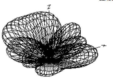
That’s a constant power density wireframe telling us with the long end north, the OCFD might “do Europe” better than the vertical. But that might come down to day and conditions.
Someone might suggest that a 160-10 meter OCFD could work. While it’s true that at 35 feet, the take off angle on the 20-meter band would come down 5 degrees closer to the horizon, there’s power dissipation as the pattern begins to “spread back toward clover leaf” from what it would be like to be a “traveling wave” antenna.
#3 End-Fed Half Wave EFHW
I don’t often use these. But they are simple. Basically a Balun (matching network) and a half-wave wire. Small coil to make many bands work. You can find them on Amazon (like this one) for under a hundred bucks. Or, try eBay or myantennas.com where there’s a wider assortment.
In John’s configuration and 35 ft mast? A 135-foot EFHW fed at 10 feet and the high side north looks like this on 20 meters at a 30 degree takeoff angle which is good for down low:

Like they say, though, no antenna is perfect. The EFHW style antenna uses the antenna feedline as the counterpoise. (pseudo ground). What this means is a tendency to get RF feedback into mic circuits. If you hear of hams getting RF “bites”? That’s RF feedback to the operating position.
Much to ponder, huh?
Keeping up on the medical stuff keeps John plenty busy. But the rest of us have fewer excuses and so if you have a penchant for “perfect antennas” under clearly definable conditions, please click here to see the rest of your weekend disappear.
Tales and Technicals, Antenna Modeling, Books God Bless Cebik.
***Bonus*** Advanced and Extra Class Senior Ham Sidebar
Ground Conductivity Maps and Retirement
Antenna model before retirement, if you haven’t already.
Get EZ-NEC (free) and model height above local ground conductivity in high resolution real mode. M3 Map of Effective Ground Conductivity in the United States for AM Broadcast Stations | Federal Communications Commission/
Now a few examples:
Dr. John’s QTH is somewhere on this map. We see – up where our mutual pal (The Major) lives – that ground conductivity is about bupkis. John’s is OK to meh depending on where he lives.
Point is, if you are torn between retirement locations, pick high ground conductivity (or salt waterfront) if you have grand designs on low HF distance (DX) ops. DXCC on a 3-day weekend kind of thing.

How this may impact “radio in retirement?” Phoenix is around a 16, but as you get up into like Mormon Lakes drops down to 8.
Choice? Better ground conductivity (and eye candy) in Scottsdale. Lower city noise floor (and better neighbors I’d wager up in Mormon Lakes. Toughie, huh?
California is so-so until you get very close to the coast. South Florida is an “8” mostly, like here. But the Gulf Coast? Take a look…

But you can get gulf storms and hurricanes, so tower costs go up. Point?
The Senior Ham Radio Retirement planner would optimize warm (but not too hot) weather, high ground conductivity, year-round gardening, and lots of public watering holes for eye candy reloading.
Oh, and reasonable wind profiles, no HOAs or local building departments. We got to a QTH with an “8” and no HOA or building department and called it good. Your grid squares of choice may vary…
(And tell reader Hank we couldn’t find the ground conductivity for lava flows on the Big Island.)
Write when 160 opens after lunch, central time.
[email protected] (ac7x)
Read the full article here